
Please do not hesitate to contact us if you would like to comment on a particular feature or ask further questions. We welcome your feedback.

Mark Pontin – Managing Director
INFORMATION GUIDELINES:
 Opto-mechanical design considerations for spaceborne lenses
Designing optical components and systems for use in space has unique challenges, and over the last decade – Resolve Optics design practices have evolved to ensure success.
The most obvious difference between general optics and space flight optical designs is because of the space environment (vacuum, low gravity, radiation, temperature extremes, launch forces etc.). An equally important challenge to overcome is due to the limitations Imposed by space launch. It currently costs tens of thousands of dollars per kilogram to put a payload in orbit, so minimising the weight of your optical design is critical. The third general constraint, which is responsible for much of the intricacies of the space flight design process, is reliability. There is little or no opportunity for servicing space optics in the event of a failure. This means your optical component or system must be ruggedly designed, constructed, and tested so that it will not fail.
Pete Chamberlain, General Manager at Resolve Optics commented “One of the first things to consider when it comes to the mechanical design of a space ready lens, is how it is going to be mounted. We advise against using the traditional threaded mounts of a standard lens, but instead suggest a custom mounting arrangement. This allows the lens to be bolted directly to a part of the hardware and in turn allow a camera / sensor to be bolted to the lens. This space ready mechanical design strategy ensures that all parts of the system are secure with no chance of working loose. Lenses for space use are subject to extremely high levels of vibrations, particularly during the launch. Consequently, it is critical that all components in the lens are tightly secured and bonded into place so that nothing can work loose. A loose glass element will quickly become damaged thereby severely impacting optical performance. All space ready lenses we produce at Resolve Optics can be qualified to a specified vibration level on our in-house ISO certified vibration/shock test centre.”
Once a lens has been successfully deployed in space it will be exposed to vacuum, radiation, and large temperature swings. All of these must be considered during the mechanical design process. It is important that all air spaces are vented, to allow air to escape in the vacuum and prevent damage to the lens. It is also important, that only vacuum safe materials are used that will not outgas in a vacuum.
Additionally, the thermal expansion of all materials must be considered during opto-mechanical design to ensure that your spaceborne lens remains in focus as the metalwork holding it in place expands and contracts with the large temperature swings it will undergo whilst in space. Cosmic radiation is well known to have a detrimental effect on many materials, including many optical glasses which will quickly turn brown and lose transmission. Therefore, it is important that only radiation stable materials are used. With lenses this means using cerium doped “non-browning” glasses, which will resist the browning effect for considerably longer than standard materials.
Learn more: click here.
VIEWPOINT:
Advances in nuclear sensors provides a lens design challenge.
 Because of the radiation hazard inherent in nuclear plants and reprocessing facilities – operators incorporate remote cameras to assist in ensuring safe and productive monitoring.
Traditionally nuclear plant operators relied upon black and white cameras based on radiation hard cathode ray tube technology to do this remote monitoring. In recent years the availability of cathode ray tubes has become a problem, making tube cameras increasingly more expensive, prompting more manufacturers of radiation hard cameras to seek an alternative sensor. Beneficially, advances in technology have improved the radiation tolerance of CMOS sensors such that they are now viable options for a large range of nuclear applications. Additional advantages of CMOS sensors include that they provide much higher resolution than tube cameras as well as delivering colour images.
Although this is all good news for nuclear plant operators, it does present a dilemma for radiation resistant lens designers and manufacturers. As tube cameras often used a 2/3-inch format, this resulted in the development of a range of optimised non browning lenses that could service the needs of most radiation tolerant camera manufacturers.
These ‘off-the-shelf’ designs enabled Resolve Optics to hold stock of the most popular lenses thereby enabling relatively short supply lead times.
However, as nuclear camera manufacturers adopted CMOS sensors, in a wide range of sizes and formats, this presented Resolve Optics with a challenge. As most nuclear monitoring applications now use slightly different CMOS sensors, they require different non browning lenses. To address this lack of a common format CMOS sensor – Resolve Optics has developed a new generation non browning lens – the Model 357 that is available in ¼-inch, 1/3-inch and 2/3-inch formats to match the performance of many high definition (HD) CMOS sensors.
Designed specifically for use with CMOS sensors in high radiation environments, our Model 357 lens range provide true high definition (HD) quality images over a 10x zoom range. Incorporating specialised non browning glasses – Model 357 lenses produce clear sharp images free of the strong yellow tint that has traditionally been a limiting issue when using radiation tolerant lenses on colour sensors. The glass used in these lenses can withstand long-term exposure to radiation up to an accumulative dose of one hundred million rad and temperatures up to 85°C without loss of transmission.
Designed as a tracking zoom lens, once a Model 357 has been set up, it will maintain focus throughout the entire zoom range. With the option for full motorised control of zoom, iris and focusing this robust zoom lens design can be adapted to deliver the full potential of HD CMOS sensors used in nuclear monitoring applications.
Learn more about the Model 357 range of non-browning lenses optimised for HD CMOS sensors for use in the nuclear industry click here.
TECHNOLOGY FORUM:
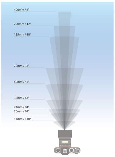 An elegant optical solution for multiple field-of-view applications.
It is quite common for a camera manufacturer to approach us with a custom lens design application where multiple fields of view are required because of the different scenarios in which the lens is to be deployed.
The obvious optical solution for such an application is a zoom lens to cover all the required focal lengths. However, zoom lenses are complex and compared to a fixed focus lens, relatively expensive. If the lens is only ever to be used at one focal length for any particular installation, then using a complex zoom lens and the cost that goes with it is unnecessary. Likewise in challenging field or process applications where a rugged optical system is required, then a zoom lens is far from ideal due to its fine tolerance moving parts.
Alternatively, if you were to use a standard fixed focus lens for a multiple field-of-view application, you would have to produce a separate design for each required operational focal length. Each of these designs would use different elements and ordering separate sets of elements of each design would also be costly.
The ideal solution is to create a single optical design that can cover all the focal lengths without the cost and complexity of a zoom lens. In situations like this it is often possible to produce an optical design for a zoom lens, but to mount the elements in fixed positions as a fixed focus lens. This approach has allowed Resolve Optics to provide different customers with a much more cost-effective solution.
Rather than having to purchase different sets of glass elements for each focal length, they can all be bundled together to provide economy of scale. The only components that would be different across the different focal lengths would be spacers, which are comparatively cheap to make in smaller quantities. This approach also allows for the lens to be ruggedised in a way that would not be possible with a functioning zoom.
Want to discuss your multiple field-of-view application? click here.
DESIGN FOCUS:
Designing lenses to withstand ingress of water and dust.
 Designing a lens assembly to prevent ingress of small particulates and water into the lens can be quite a challenge.
Ingress protection (IP) is typically required when rugged lenses are used in environments subject to high humidity/moisture, sputter, dust, or small particles, and where space to fully enclose the lens and camera is not possible.
Ingress protection ratings are specified with two digits, which make up the IP rating according to the IEC 60529 standard. The first digit describes the level of protection against solids and particles and ranges from zero to six. If a component has not been tested for protection against solid intrusion, the first digit is changed to an X. The second digit indicates the level of protection from moisture and ranges from zero to nine.
Designing a fixed focus lens with a fixed aperture to be IP rated can be achieved by simply making sure the lens body is sealed using silicone sealant or o-rings. Ingress protection becomes more of a challenge when your application requires a zoom lens or a lens with a focusing mount or an adjustable iris. Such scenario’s present problems that are not easy to overcome. In cases where the lenses have moving parts, we recommend that IP rating is achieved by way of a housing rather than the lens itself. It is obviously, much easier to seal a simple housing than it is to make a complex lens watertight.
However, there are applications, where due to space constraints, there just isn’t room enough for a separate housing. Faced with this, Resolve Optics has experience of designing the outer body of the lens to act like the housing so that high humidity, moisture, and particulates cannot penetrate and degrade the performance of the lens or camera.
To read a case study describing an IP-rated lens assembly designed by Resolve Optics please click here.
PROJECT REPORT:
Lens innovations enable development of 1GB aerial surveillance camera.
 Traditionally aerial surveillance cameras have offered limited resolution and only a relatively narrow target view. As a result, data quality and how much surveillance data a user could acquire when the sky is clear suffered.
As part of an EU multi-partner project – Resolve Optics was asked to design and develop 3 ultra-large format, low distortion lenses to be used on a single camera capable of recording 1 gigabit images. This aerial surveillance and photogrammetry camera has enabled large areas of ground to be imaged in a single pass thereby reducing the time an aircraft had to spend flying back and forth, thereby reducing cost, and saving time.
To gather so much information the camera used an array of 18 ultra-large format sensors. The sensors were positioned so that each of the three camera lenses would cover 6 sensors at a time with enough overlap that the resulting images could be stitched together to produce one very large high-resolution image.
To ensure accurate image stitching the lenses were required to have very tightly tolerance magnification and distortion specifications. To demonstrate this demanding lens quality – Resolve Optics used their fully automated MTF test bench to provide distortion and magnification mapping on each supplied lens with the data provided to the customer as an Excel file.
As part of an aerial surveillance camera system – the developed lenses also had to offer very accurate focusing. To achieve this the image plane positions were accurately measured and any deviation from its 185mm register was corrected using a stainless-steel setting ring that was ground to a precise thickness. The required accuracy of the lenses was such that the melt data for the raw glass used to produce each optical component had to be checked. This was to ensure any variance in density and refractive index was within tolerance and any deviations then had to be corrected with slight changes to the element radii and air spaces.
To learn more about our specialist lens design and development capabilities click here.
BREAKING NEWS
 Industry interview ‘Update on materials inspection and sorting’.
An important part of quality assurance of food, produce and grain, is how inspection and sorting systems are used to help weed out products not fit for consumption. In a new interview with PCN Europe – Mark Pontin discussed why inspection and sorting system manufacturers have standardised on the SWIR waveband for optical inspection and the benefits of using optimised rather than off-the-shelf lenses.
Read interview in full click here.
Lenses in action.
 One of the most visited pages on our web site is the case study bibliography. Our aim with this web page is to provide you with details of our custom designed lenses in action in a real-world context. Even though the majority of our 28 listed lens design and manufacture projects are subject to confidentiality the case studies are still able to provide you with a feel of some of the application challenges, the optical solutions we have proposed and the benefits our customers have gained from the produced special lens or optical system.
Review case studies: click here.
A date for your diary.
 VISION 2024 will be Europe’s most important international meeting point to experience the latest products, technologies, and trend themes in machine vision. At VISION, you will be able to discuss your activities and requirements with the experts and gather ideas for innovative applications. Whether you are looking for an optimised custom lens or off-the-shelf optics for your sensor, camera, or instrument system we invite you to come and talk with Resolve Optics experienced team of specialists on our booth 10G44.
We look forward to seeing you at VISION 2024, stand no.10G44, click here.
New cleanroom facilities.
 We are constantly looking at ways of improving our product quality. As part of this ongoing program of continuous improvement we have just completed a major refurbishment of our clean room. In addition to installing a new, higher specification air circulation / filtration system, we have also installed new optical assembly benches with easy clean surfaces throughout the production facility. Through investing in a better, cleaner production area we are looking to further improve the quality of lenses and optical systems we deliver to our customers.
Learn more: click here.
THE LAST WORD:
NASA: what’s next for Mars exploration.
 Over the next two decades – NASA’s Mars Exploration Program will focus on its science-driven systemic approach to achieving the following strategic goals: exploring for potential life, understanding the geology and climate of Mars, and preparation for human exploration.
Like the Moon, Mars is a rich destination for scientific discovery and a driver of new technologies that will enable humans to travel and explore far from Earth. When astronauts travel to Mars and back, their space vehicle will return home having travelled more than a billion miles.
To make this all possible, NASA has established a series of projects to look at key challenges for people to live and work on Mars including oxygen, food, water, power, spacesuits, communications, and shelter.
This editorial feature was first published on the NASA website.
Learn more: click here.